
Building a Wooden Lobster Boat
John’s Bay Boat Company, Part I
Peter Kass has had a life long interest in wooden boats. Thirty-five years after beginning his apprenticeship at the Harvey Gamage Yard in South Bristol and two years at Goudy and Stevens, it might be said his boat building has taken on a life of it’s own. The high standards of quality craftsmanship and attention to every practical detail has brought him a customer base that approaches being a following. John’s Bay boats are known to be stron g and durable. At the same time designed to be stable, comfortable and good looking.
John’s Bay builds working fishing boats and pleasure boats. The building methods might be called improved traditional. From use of the half model to bronze keel bolts to custom hardware to the seventh coat of spar varnish, it’s all about the details.
Kass still builds one boat at a time. As much to continue enjoying the building process, which he clearly does, as to not overlook attention to the smallest detail. He is the designer, engineer and hands on master craftsman involved in every step of the building process. Some of his crew have been with him for decades.
This photo essay highlights some of the steps in an ages old building process. The work requires high level skills in engineering, intuition, architecture, materials, tools, and a lot of practice.
Special thanks to Walt Barrows, a photographer and admirer of Kass’s work, for granting the use of his photographs for this story. The boat in the photos was built in the winter of 2014-2015.
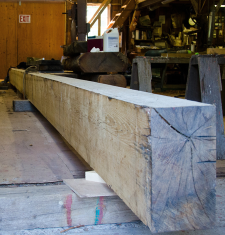
The 36' x 7" x 13" white oak keel is delivered to the shop from a sawmill in southeast Connecticut.
It will be trimmed to 34' for the 46' boat that will be built on it.
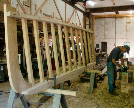
The assembled stern frame. Curved parts are cut using patterns drawn from lofting and
the lines transferred to the oak parts. They are sawn on a bandsaw.
Joints between these parts are also cut on the bandsaw then planed for a tight well fitted joint.
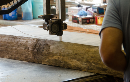
Band sawing the 5" thick stem piece.
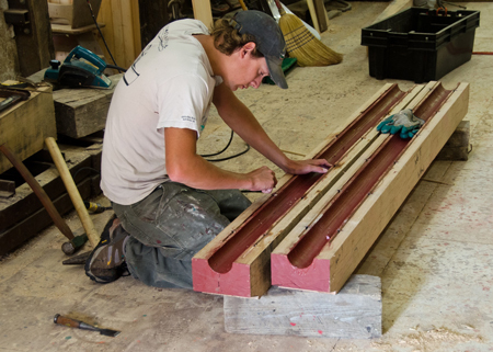
The two piece shaft log will be stacked between the other pieces of the keel. The propeller shaft, a half inch smaller in diameter than the shaft hole, will pass through it. The hole is created on a table saw cutting the length of the piece and repeating it while deepening the cut in 1/8" depths until the half circle shape is formed. A wooden plane with a curved base and cutting edge is used to smooth the stepped surface before priming. The two halves are assembled with water seal splines. Seven keel bolt holes are drilled on both sides of the hole. The keel bolt holes are drilled on a drill press for precision and are used as a drilling pattern on the keel it will be bolted to. The space between the propeller shaft and the wood fills with water to cool the rotating shaft. A stuffing box packed with wax impregnated flax seals the shaft log on the inside of the boat.
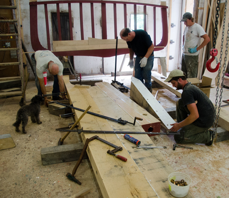
Assembling the keel parts. Left to right: Sam Jones, Peter Kass, David Thorpe, Andy Dickens. Keel bolts are driven further as each keel piece is added. The bolts project an inch as a guide for the next keel piece. Fifi, left foreground checks Sam’s work and stands to the left of projecting keel bolts. Parts L to R, keel, deadwood beveled to properly angle adjacent shaft log, Kass and Thorpe, center, stand over the jib piece ready to flip it to align the holes with the bolts projecting from the shaft log. The jib piece is beveled for the proper horn timber angle. Behind Kass and Thorpe is the horn timber which will overhang the keel beyond the propeller, forming the flatter area in a finished hull.
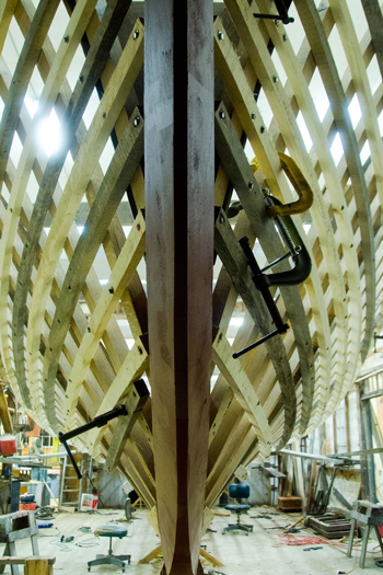
Chisels and small rabbet planes are used to cut the rabbet or groove that the edges and ends of planking will fit into. On the inside of the curve are the ends of the bronze bolts holding together the two stem pieces that meet at that point. Cuts in the compound curves of the rabbet are guided by lofted lines and experience with the cutting tools.
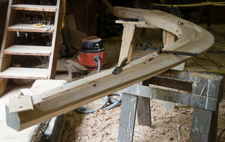
From bottom up keel parts, the keel, the deadwood with beveled end, the shaft log,
the jib piece with beveled end, and the horn timber.
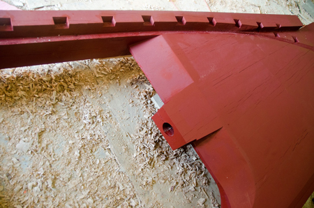
Shaft log center with beveled deadwood and jib pieces on either side. The far end of these two pieces are beveled to a point to improve water flow to the propeller. A technique in common use for the last ten years or so. Calvin Beal of Beals is said to be the originator of the improvement. It results in smoother running and less cavitation of the propeller blades. Horn timber above with pockets cut.
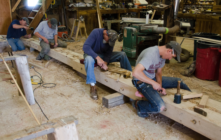
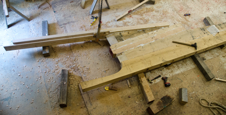
Left to right, cutting pockets Peter Kass, Andy Dickens, Sam Jones and Jeff Hanley. After the rabbet is cut, pockets are cut in the keel along the edge of the rabbet. Pockets are partially drilled and finished square with a chisel. This assembly will have 108 pockets. Steam bent frames ends will be fitted in the pockets and screwed in place.
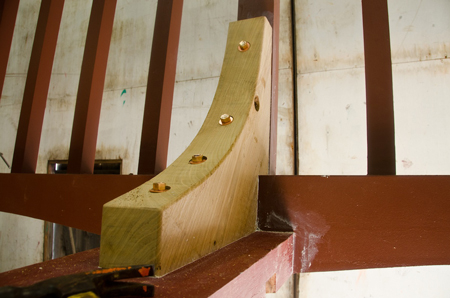
Stern knee bronze bolted to keel and stern before being painted.